sâmbătă, 18 aprilie 2009

5. Solving the problems

First of all i must reduced the voltage variations on the power supply output.
To stabilize the voltage i used a zener diode of 12V (5W) connected on the base of a 2N3055 transistor,
followed by a LM2940T-5.0 regulator.
Another problem that a i have to solve it is to eliminate the electromagnetic influences. This can be done beginning with the design of the circuit/pcb . It is important to:
a) place the controller in to a metallic box
b) all the conductors (power and signal) must be shielded.
c) the pcb must designed with ground plane and components must be SMD if it is possible.
d) avoid ground loop.

I change the controller 16F876 with 18F2550 which has same layout (28pins). The 16F876 has some difficulties at memory access because the memory are split in banks. The 18F2550 memory can be allocated withowt problems. Another advantage of 18F2550 is 32K program memory.


joi, 16 aprilie 2009

4. The problems

Hello.

Aware that i can't know all the problems that will i must face to, I opened a topic on two forums that I entered more often.After discussions
on UrbanRiders.ro and Motociclism.ro I came to the
following conclusions:

a) for controller stability the power supply must be well designed. The bike battery provide 12v DC, but in reality it may happen that this voltage
to grow up to 100V (for a short time of course) due to alternator dysfunction or when some loads (like headlights) are turned off.

b) Must use a MAP sensor to a better control of the engine. Initially I wanted to use the TPS sensor to calculate the amount of fuel to be injected
(see ALPHA-N) but I realized that will be hard to control the engine speed because the amount of air that enters the engine is not linearly
proportional to acceleration position. The amount of air that enters in the cylinder is dependent on the atmospheric pressure and air temperature.
So a MAP sensor is much better than one TPS.

c) I need to design another block for the STEPPER actuator to control the "Fast idle" function. The "Fast Idle" function means the higher speed at
which an engine idles during warm-up. When first started, a cold engine needs more throttle opening to idle properly. On carbureted engines without computer
idle speed control, a set of cam lobes on the choke linkage provides a fast idle speed during engine warm-up.

d) Is very important to not hang or restarts the controller. I understand that micro-controllers (especially the microchip) can easily be restarted due to
electromagnetic interference or from variations in supply voltage. For example, a strong electromagnetic source it is the horn!

miercuri, 15 aprilie 2009

3. First attempts

I start working and i have established a first direction.

I use:
1. PIC16F876 controller
2. engine temperature sensor
3. TPS - throttle position sensor
4. lambda probe (oxygen sensor)
5. engine speed and position will be read from the ignition coil (negative connector).
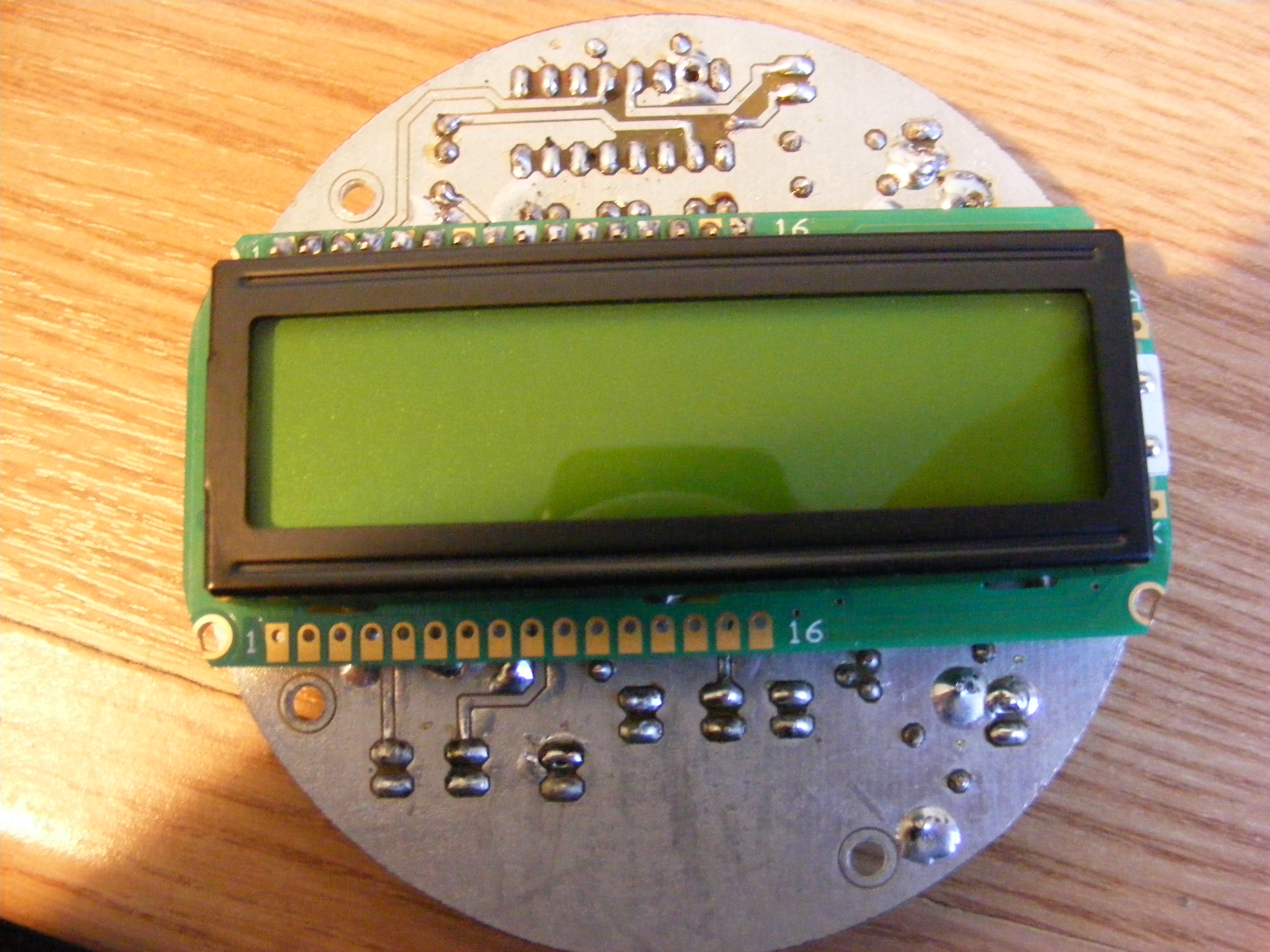
Connected to the controller will be a 16x2 LCD display.
The first test looks like this:


PIC16F876:
- RISC CPU
- max 20MHz
- 8K program memory
- 368 bytes RAM
- 256 bytes EEPROM
- 5 analogic input
- 17 digital I/O At that time I considered enough the above configuration.
So I connected the LCD in 8bit mode (11 digital pins), I put a 2
buttons (another 2 digital pins), two entries for the two signals from the
coils, and two outputs for the two injectors. In total 17 digital ports
occupied. I tested with a temperature sensor (termistor) => tests were a success. LCD's work correctly, A/D converters works well ... everything was OK.
At that time did not know of the two EFI systems, ALPHA-N and SpeedDendity. For simplicity i choose to calculate the injector timing from engine speed and throttle position (ALPHA-N type system).
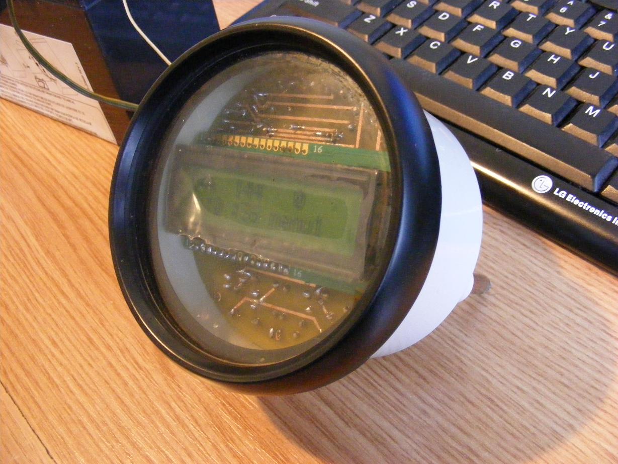
I intend that all the systems (controller, LCD, the power block and the sensors) to fit in place of one of the two watches on-board.
For simulating and design the pcb i used a series of software in their demo version but most easily to use was "Circuit Simulator Applet".
You can see in the picture bellow some stages of the design.


The scheme contains:
- two entries for the signals from coils, each controlled by one transistor BC547
- an LM7805 voltage regulator
- Pic 16F876 controller
- LCD 16x2
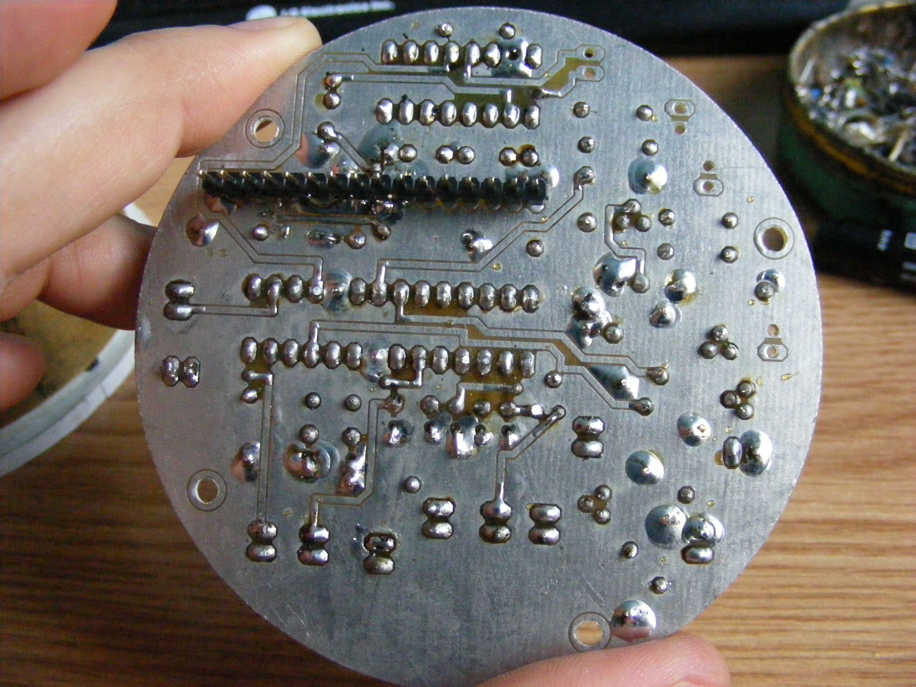
PCB is double plated and I made it using Press'n'Peel process
(which I have never overdone, I broke 3 PCB until I get one in the pictures).
I did some tests directly on the bike.I removed the spark plugs, I connected the circuit to coil, I powered the controller
by an external battery and i turn on the start switch.i did not done the tests with running engine, because probably,
all my neighbors starts to panic. Over the winter my garage is at the 3rd floor next to my door. So, without spark plug
the starter turns the engine faster and the LCD displays 200-360 rot/min.
At that time was a success.
Finally, a circuit designed and created by me from scratch, works!


In the mean time the throttle body arrived from USA. It is a keihin Throttle body from an Kawasaki ninja. It is equipped
with two bosh injectors, fuel rails, TPS sensor , FIP(fast idle position) sensor and stepper actuator.I bought it from
eBay and cost me 10$ + 40$ shipping = 50$ and it is in good shape.


2. The theory

Hello.
The project went through several phases.
The first phase was the collecting information about EFI=electronic fuel injection system. If I had to explain in two words what would come out is something like this: EFI is a system which controls the gas and air mixture needed in combustion engines! Basically EFI replaces the old carburetor, and is a much more complex.
EFI system is composed of several main elements:
- ECU - central computing unit => is a computer which controls the engine.
- Sensors => temperature, pressure, position of the acceleration (TPS), speed, oxygen, etc. ...
- Throttle Body , injectors and air controlling system
- Injection pump

The flow control:
Computer (ECU) read sensors, analyze the values and sends an electrical rectangular impulse to the injectors. Duration and time of the impulse is based on sensors data entry and tables from ECU memory. There are two broad categories of EFI systems:
a) "Alpha-N" uses as input the acceleration position (TPS) and engine speed to calculate the amount of fuel injected. The system is designed for sports competitions.
b) "Speed Density" use as entry data from MAP (manifold absolute pressure) sensor and engine speed. MAP is a pressure sensor (the value returned is proportional to the difference between atmospheric pressure and intake pressure) on which is calculated the amount of air that enters in engine. This system it is recommended for public roads.

Both categories can be with "closed loop" or "open loop" according to the presence / absence of oxygen sensor which monitors exhaust emissions. Also the temperature sensor is needed.

All these information are available on the net. I just summarize what I understood.

1. Cause and effect

Hello.
Time is precious, so, i go directly to the topic. What I want to do is an improvement for my bike. I will replace the carburetor with an electronic fuel injection system.

There are several reasons why I want to do this:

1. fuel economy.
2. desire to change the bike. If you can not change, the next option is to modify it.
3. increase performance.
4. a very good reason to learn something new.
5. the satisfaction when you realize something.
6. bike will be unique and I think it will have higher value (at least sentimental).

At this time the project is in the stage of "desk testing". I will come later with new pictures and information.