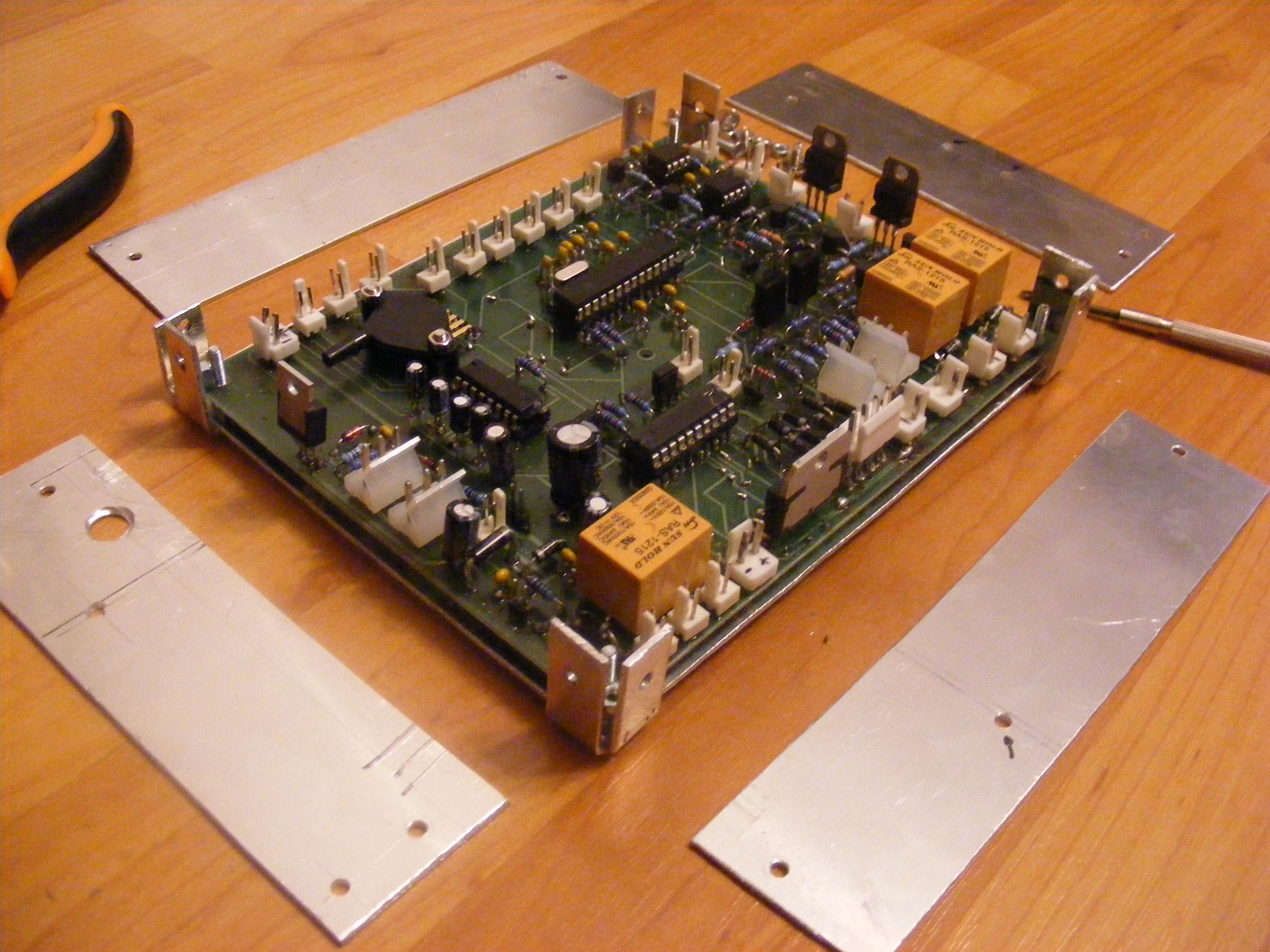
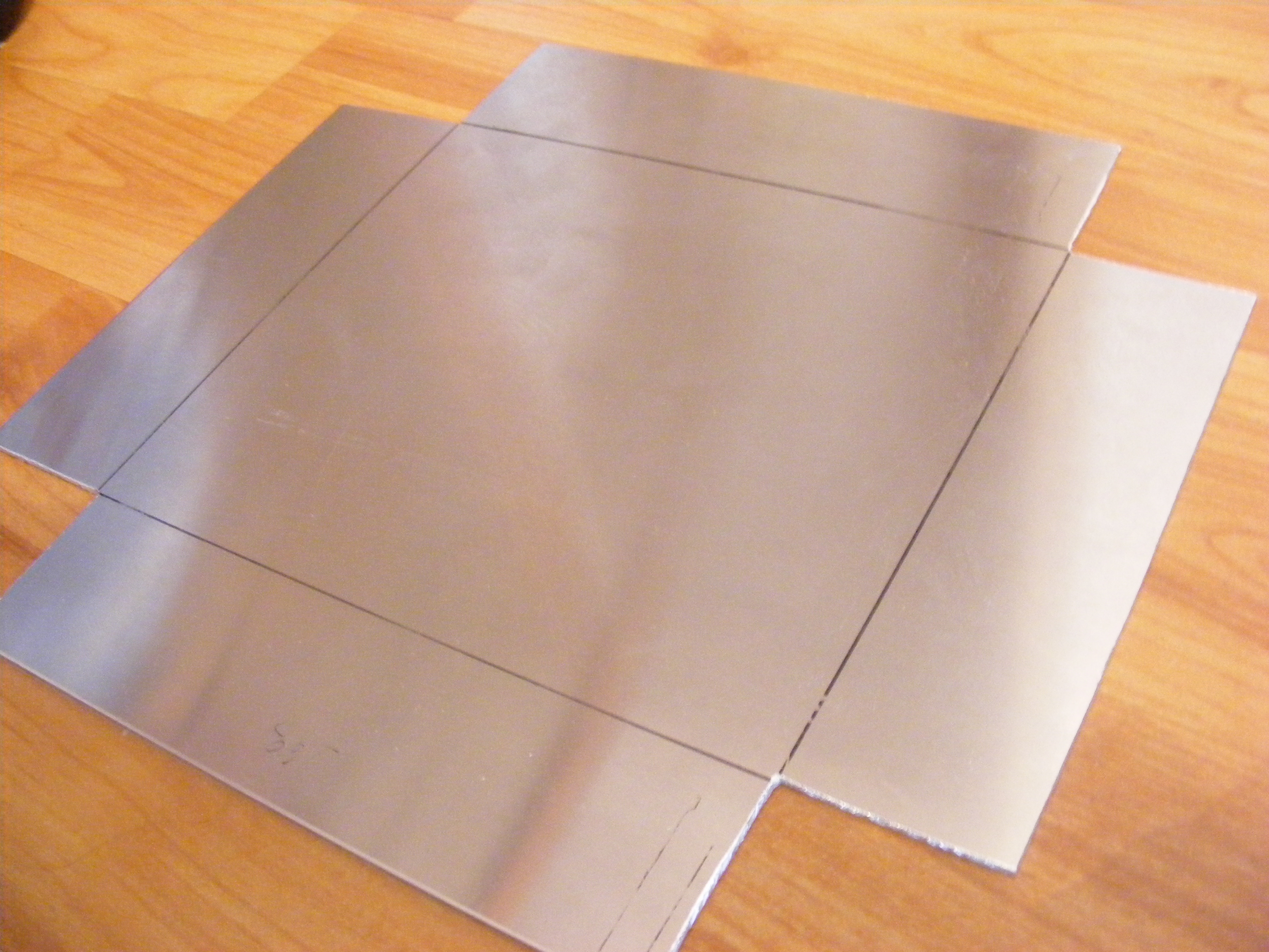
After many not successful tries to fix the problem with tachometer i have decided to remove all the electronics from the bike , and redesign the circuit. I must to test and fix all the problems starting from the design.
I must fix some problems:
- the size of the metallic box (which is an ATX power supply from an old computer), i have to reduce the size.
- reduce the number of connections between the two PCB (you can see in the picture above, the wire mess between controller and power source), This can be done by using only one PCB.
- The main problem it is the wrong reading of the RPM!
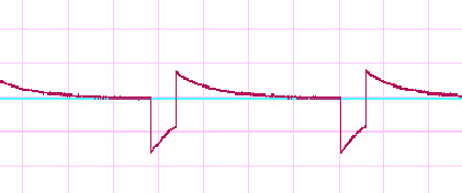
I decided first to visualize Variable Reluctance sensor output signal. Because i don't have an oscilloscope i use an external USB sound card (i could have used the sound card of my laptop but it is safer with an external card).The generic sound card can capture signals up to 20KHz(aprox.). The engine it is designed to go up to 12000 RPM, equivalent with 200Hz => I can use the sound card!
I start the engine and i pick up the signal from sensors throw an 3M ohms resistor. The signal can be visualized with
zelscope or
virtins. I used the trial version and you can see the result in following image:
The above signal it is the typical signal for Variable Reluctance sensors. You can find
here some info about this sensor and how to calculate the RPM (i tried all that methods to eliminate the reading error ).
Searching on the net for the best circuit to transform the sinusoidal input signal into rectangular or pulse signal. I found two IC that can do this work: LM2907 and LM1815 .
I choose first to test the LM2907. The test schematics and response looks like this:
The above tests was made with engine running at idle RPM, and all the components used was just like that in the schematics. I choose to use the second schematics connected with the controller (all the electronics still working ) and the results was pretty good. The RPM displayed was stable and according to engine speed.